
Modbus is a communication protocol for transmitting information between electronic devices over serial lines (original version) or via the Ethernet, and is commonly used in process and factory Automation. While it’s an open protocol
RS-232
If you decide to apply Modbus using RS-232, you have a maximum distance between the master and slave of 15 meters. And you can have only one master and one slave, known as a point-to-point or peer-to-peer connection.
RS-422 and RS-485
Now, if you use RS-422 or RS-485, then you’ll get more flexibility. Here you can have one master and many slaves. The network has a cable structure of Tx+/Tx– to transmit and Rx+/Rx – and a ground to receive.
You’ll see more RS-485 than RS-422, as the former allows up to 32 slaves without a repeater. However, you can get up to 247 slaves if you apply repeaters in the network (maximum length = 1200 meters).
RS-485 setup
When you add devices to a network, you need all devices in the same baud or bit rate, because the protocol is asynchronous. Usually, you can get a normal speed between 9600 to 19200, but you can set up faster speeds from 300 to 100000.
Modbus ASCII (American Standard Code for
Information Interchange)
You can set masters up to communicate with ASCII or RTU. In ASCII, each 8-bit unit transmits as two ASCII characters. ASCII can have up to one second between characters without creating an error.
Modbus RTU (Remote Terminal Unit)
If you set the master up with RTU, each unit contains two 4-bit hexadecimal characters. RTU offers better data throughput than ASCII because of its excellent character density.
Modbus TCP/IP
In 1999, Modbus TCP/IP emerged to handle the new reality of Ethernet protocols in industrial applications. TCP/IP uses the internet to transport data, and the Modbus instructions come through the TCP/IP. This protocol was developed for the internet and offers interoperability among vendors.
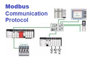
Modbus serial protocol (the original version) is a master/slave protocol, e.g. one master that controls the Modbus data transactions with multiple slaves that respond to the master’s requests to read from or write data to the slaves. Modbus TCP, also known as Modbus TCP/IP, uses a client/server architecture. These network architectures are shown Figures 1 and 2.

In a standard Modbus serial network, there is one master and as many as 247 slaves, each with a unique slave address. Modbus TCP is typically implemented on an Ethernet network, and data transactions from a Modbus client are directed toward a Modbus server via an IP address.
Modbus comes in several varieties including Serial RTU, Serial ASCII, TCP/IP and UDP/IP. Modbus dialects, such as Enron, Daniel and Pemex Modbus, have arisen due to people modifying standard Modbus to handle floating-point data, long-integer data, and other data requirements. Reading the Modbus interface and slave documentation is key to understanding and implementing these types of Modbus networks and to mixing different manufacturer’s devices in the same Modbus network, which should be carefully done.
The original fieldbus
The Modbus protocol is the grandfather of modern fieldbuses. Modbus’s popularity is due to its simplicity, its openness and ubiquitous nature—it’s used everywhere. It has withstood the test
of time and is still kicking after almost four decades. Modbus was originally published by Modicon in 1979, primarily for use with its own PLCs. When industrial Ethernet appeared, Modbus TCP was developed, retaining much of Modbus’ simplicity in a TCP/IP wrapper.

The most commonly used form of Modbus protocol is RTU over RS-485. Modbus RTU is a relatively simple serial protocol that can be transmitted via traditional UART technology. Data is transmitted in 8-bit bytes, one bit at a time, at baud rates ranging from 1200 bits per second (baud) to 115200 bits per second. The majority of Modbus RTU devices only support speeds up to 38400 bits per second.

A Modbus RTU network has one Master and one or more Slaves. Each slave has a unique 8-bit device address or unit number. Packets sent by the master include the address of the slave the message is intended for. The slave must respond only if its address is recognized, and must respond within a certain time period or the master will call it a “no response” error.
Each exchange of data consists of a request from the master, followed by a response from the slave. Each data packet, whether request or response, begins with the device address or slave address, followed by function code, followed by parameters defining what is being asked for or provided. The exact formats of the request and response are documented in detail in the Modbus protocol specification. The general outline of each request and response is illustrated below.

Register types and reference ranges recognized with Modicon notation are as follows:
0x = Coil = 00001-09999
1x = Discrete Input = 10001-19999
3x = Input Register = 30001-39999
4x = Holding Register = 40001-49999
On occasion, it is necessary to access more than 10,000 of a register type. Based on the original convention, there is another de facto standard that looks very similar. Additional register types and reference ranges recognized with Modicon notation are as follows:
0x = Coil = 000001-065535
1x = Discrete Input = 100001-165535
3x = Input Register = 300001-365535
4x = Holding Register = 400001-465535
When using the extended register referencing, it is mandatory that all register references be exactly six digits. This is the only way Babel Buster will know the difference between holding register 40001 and coil 40001. If coil 40001 is the target, it must appear as 040001.
Modbus Message Error Handling
The slave’s normal response simply echoes the original function code of the request, but the slave’s error response returns a code that is equivalent to the original function code with the most significant bit set to logic 1.
For example, the “Read Holding Registers” command (Function Code 03) has the function code with 1 byte containing 8 bits is binary 0000 0011 (03 Hex). If the slave device accepts the request without error, it will return the same code in its response.
However, if an error occurs, the slave will return 1 byte containing 8 binary bits 1000 0011 (the most significant bit set to logic 1) in the “function code” field and appends a unique code (Exception Code) in the “data” field of the response message that tells the master device what kind of error occurred, or the reason for the error.
plc training in chennai plc scada training in chennai plc scada dcs training in chennai DCS Training in chennai Industrial Automation training in chennai Industrial Automation training institute in chennai plc training institute in chennai Good PLC Training institute in chennai plc training with placements in chennai plc scada training placements in chennai DeltaV DCS Training Honeywell DCS Training ABB 800xA DCS Training Automation training in chennai PLC Scada Training Institutes in Chennai PLC Training in Chennai PLC Training Center in Chennai Best PLC Training Institute in Chennai