PLC Training in Chennai
- February 28, 2019
- Excel_57
- 0

PLC Training
The basic architecture of a PLC is important to understand. It is crucial to know about the basic PLC hardware components that are inside PLC, because it will make your understanding of the PLC much easier. The hardware components are the physical building blocks of the PLC.
4 categories of PLC hardware
The PLC is designed with some basic hardware components, that each adds it’s own function to the PLC. We can divide those components into four categories:
- CPU (central processing unit, the microprocessor, memory)
- Input electronics
- Output electronics
- Power Supply
Of course most PLC’s consists of many components but these for are the most important ones. If you know about these four main hardware components in the PLC that should do it.
CPU – the PLC processor
This is the brain of the PLC, where all calculations go on. To be more precise, this is the part that runs the PLC program. You might have hear about microprocessors. Microprocessors are integrated circuits that runs programs. Microprocessors are everywhere and the most known microprocessor is the one all computers have. The Intel Core i7 is a microprocessor. A very advanced one. The brain of a PLC is also a microprocessor, but less powerful than the ones in computers.
The microprocessor is where the PLC program processes all the input and output signals.
The memory of a PLC
Where does the PLC save all it’s information? The PLC has memory like a computer, called RAM or random access memory. The PLC usually also have some memory called ROM and EEPROM. There is a slight difference between these types of memory in the PLC and it has to do with erasing the memory:
RAM (random access memory)
Temporary memory in use when running the PLC program. This memory is volatile which means that it will be erased everytime the power is off.
ROM (read only memory)
Permanent memory in the PLC used to store the operating system of the PLC. The operating system makes the PLC able to execute your PLC program.
EEPROM (electronically erasable programmable read only memory)
This is a permanent memory just like the ROM, but with one crucial difference: it can be erased and reused. The EEPROM can be erased electronically and used again. Normally this is where your PLC program is stored in the PLC.
PLC input electronics
The microprocessor has a lot of both inputs and outputs, but they usually works at around 5 volts. And since the standard voltage level in many input devices are 24 volts, the PLC needs some input electronics to we can connect devices to the inputs. The input electronics are an electronic circuit between the connection terminals of the PLC and the inputs on the microprocessor.
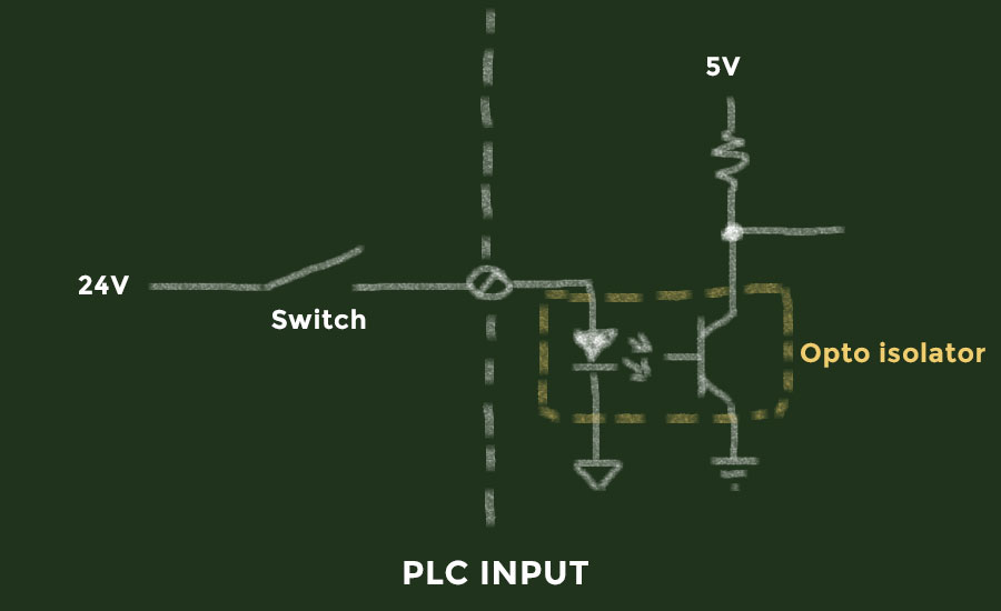
The most important part of the input electronics is the opto-isolator or the optocoupler. The opto-isolator works by converting an electrical signal to light, and then enabling another electrical signal. It consists of a light emitting diode (LED) and a phototransistor. The LED works by emitting light when connected to a power source and the phototransistor opens up for current flow when exposed to light.
Let me illustrate how the opto-isolator works by drawing a simple electrical circuit of a microprocessor input:

The voltage we use for our sensor is 24 volts. When we connect the signal wire on the sensor to the PLC input terminal we are in fact connecting it to an opto-isolator. So, when the sensor is activated we will have 24 volts activating the LED inside the opto-isolator. The phototransistor will then be activated by the exposure of light. The 5 volt circuit for the microprocessor is connected to the phototransistor in the opto-isolator. This means that the input PA1 is activated with 5 volts when our 24 volt sensor is activated.
The idea of using an opto-isolator is to isolate the two circuits to protect the microprocessor from high voltages. Most opto-isolators can take a peak voltage of several kilovolts, and that will be the protection of the inputs on the microprocessor which usually operates at 0-5 volts.
PLC output electronics
Microprocessors have the same problem with outputs as with inputs. That’s why all PLC’s contain output electronics between the microprocessor outputs and the output terminals on the PLC.
An important part of the output electronics is the opto-isolator, just like in the input electronics. The function of the opto-isolator here is also to isolate the two electrical circuits. The 5 volt circuit for the microprocessor and the external circuit for the outputs on the PLC.

As you can see the power supply used to supply the load connected to the output (L) is an external power supply. The opto-isolator is again used to isolate the internal PLC circuit from the output circuit.
PLC power supply
Most PLC’s need one or more power supplies for the CPU and sometimes for the inputs and outputs. Since some PLC’s will require a direct current power supply, you might need a power supply for your PLC. All the PLC manufacturers make power supplies for their PLC’s, but you can use your own power supply as long as it provides the correct voltage level. Some of the PLC’s have a build-in power supplies. This means that you can connect an alternating current (AC) power supply to your PLC.
Of all the PLC hardware the first one you always have to connect is the power supply. Make sure you do it right and be careful because you can destroy the PLC.
So, how do you know what type of power supply you should use?
Answer: Always look in the datasheet of the PLC. You will find all the information about the necessary power source and other useful data about the PLC.
Most PLC manufacturers today have the datasheets and user manuals for the PLC’s and the power suplies online free to download. A quick search on the name of your PLC and you should have the user manual.

